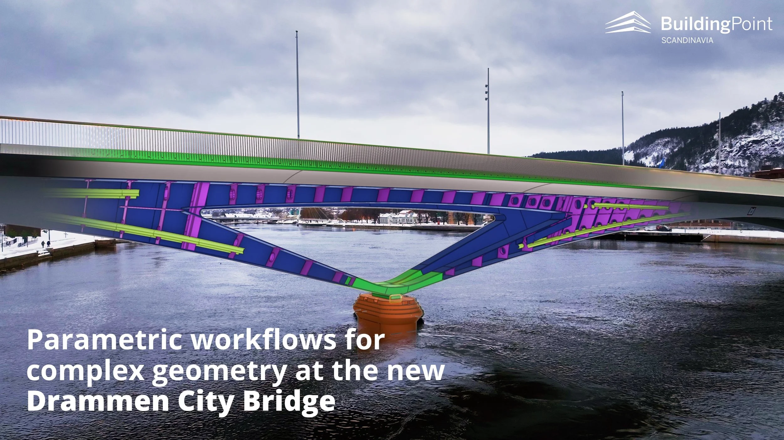
Summer interns adapts Tekla for Timber
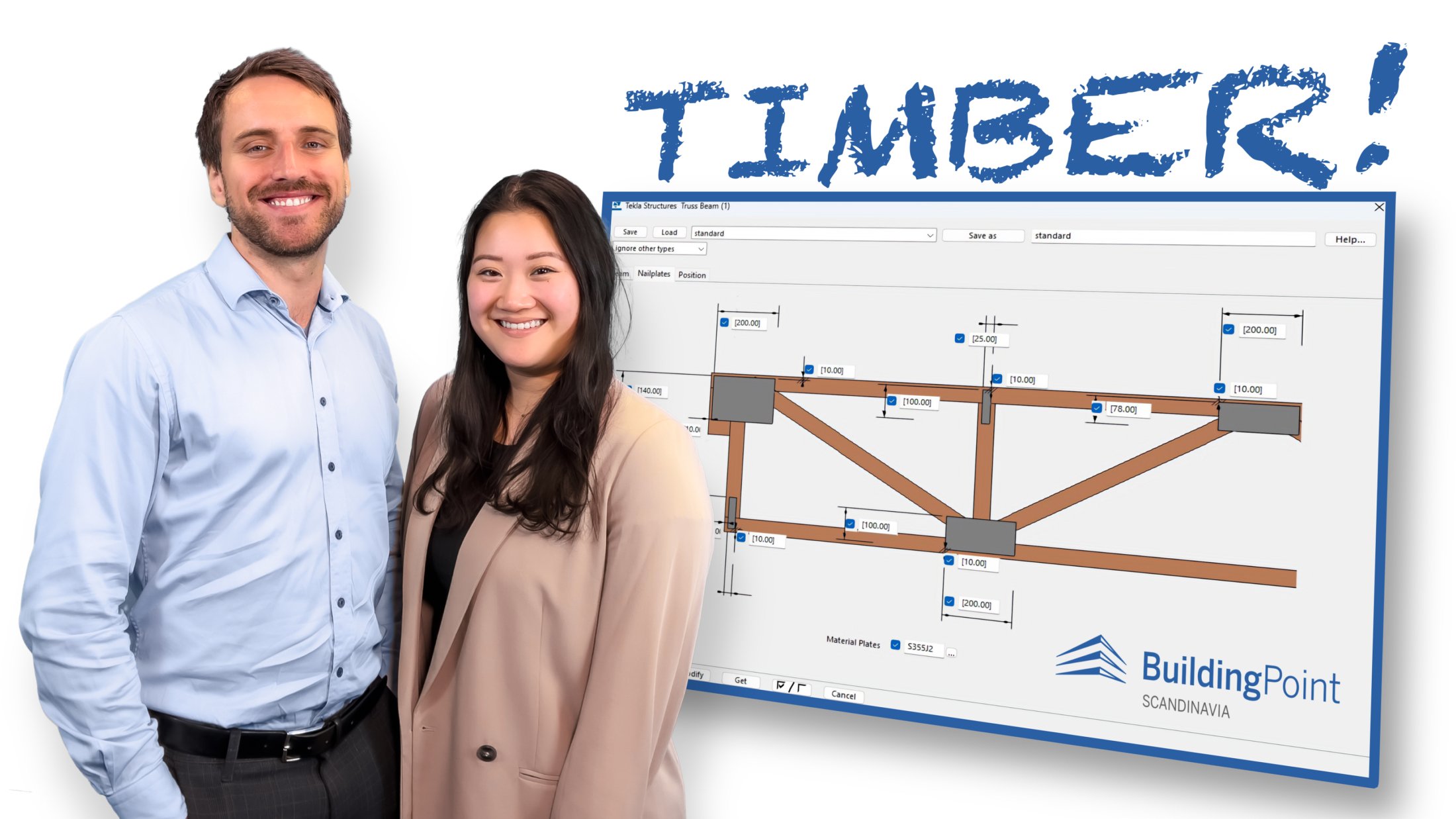
IMAGE: Summer interns 2023: Anders Sjøberg and Hannah Rønneberg from NTNU

Written by:
Hannah Rønneberg
and Anders Sjøberg
The use of wood/timber in the load-bearing structures of buildings and other structures is increasing.
The BIM software Tekla Structures is traditionally widely used in steel and concrete structures, but has in recent years also been used for the design of buildings and other timber structures, such as Finansparken in Stavanger.
Summer students Hannah Rønneberg and Anders Sjøberg from NTNU at Gjøvik were given the task of adapting Tekla Structures to timber. The students wanted, in collaboration with the industry, to develop the Tekla user interface and workflow with automation that offers a more intuitive and seamless use of wood/timber materials and typical timber components within Tekla!

IMAGE: Hannah Rønneberg and Anders Sjøberg presenting the project to the BuildingPoint Scandinavia management team.
Based on a "wish list" from industry, they were to decompose the problem and define subproblems. With a background as engineering students in civil and structural engineering, they have worked with functions that the interface should have to facilitate more efficient use of Tekla for the design of timber structures.
The team contacted several players in the industry (see list at the bottom of the article) and gained an understanding of which areas to prioritize.
Timber as a building material
Solid timber and glulam in load-bearing structures open up for many new and exciting solutions and expressions, and the technical possibilities are developing at great speed. Industrial production and industrial timber construction provide new competitive advantages.
Solid timber is also climate and environmentally friendly, and contributes to increased sustainability with methods and materials that take the environment into account throughout the building's life cycle. It requires little energy and results in low CO2 emissions compared to other materials such as steel and concrete.

IMAGE: Finansparken in Stavanger, a fantastic timber project that was submitted to the Tekla BIM Awards competition. Courtesy of Degree of Freedom,
THE PROJECT
New features in Tekla
The team has proposed several new features in Tekla. Some features are already finished, some are in progress, or just sketched out in a plan.
Material and profiles
A large material catalog with various products from the timber products industry and their mean densities has been added as a .lis file. This allows the user to choose the vast majority of material qualities, all the way down to C14 for construction timber.
Both "hardwood" such as birch and oak as well as "softwood" such as spruce and pine, but also glulam all the way down to C20 quality for both combined and homogeneous products have been added. Mean values for CLT (cross-laminated timber) are also added in addition to T15 and T22. Different densities have also been defined in English for Misc, for example SDF, MDF and HDF along with plaster, mineral wool etc.
Entering these material types as the basis for a "Timber ribbon" in the user interface where eg. "Beam" or "Column" is selected is on the list of things that can be implemented.
A profile catalogue has also been added for base dimensions used when constructing wooden structures.
IMAGE: Tekla Structures Profile Catalog showing different timber profiles. (Click for larger picture)
IMAGE: Tekla Structures Profile Catalog showing different timber material qualities and densities. (Click for larger picture)
IMAGE: Tekla Structures material list listing the various dimensions and materials used. (Click for larger picture)
Material Take Off (MTO)
A material list is added in English that uses densities to calculate weight while simultaneously listing the various dimensions and materials used.
Future reports for e.g., fastener reports and component reports are also desirable to have in the future.
Tekla Component:
Visible/Non-Visible Detailing
In solid timber production, both the fiber direction of the slats and the surface treatment of the elements are chosen in relation to the application and whether they are mounted visibly or non-visible.
The team has prepared a plan for a component in Tekla that solves this. The component should be able to select wall and covering elements in the model and allow designers to indicate what are visible sides and what are non-visible sides, along with which direction the fibers are located in the element. These indications will be shown in both planes and sections in drawings extracted from Tekla Structures.
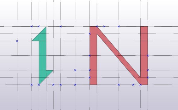
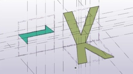
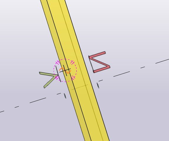
Initially, the component should allow the user to select surfaces of their element as Visible (V - Visual) and Non-Visual (N - Non-Visual) along with fiber direction arrows in the width or longitudinal direction.
Tekla Component:
Lattice beam and hollow box elements
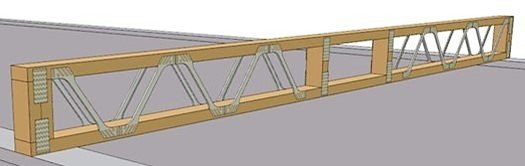
The lattice beam is a way of manufacturing floor elements that are increasing in popularity. This is an efficient design in terms of weight, strength and production and installation time.
A way to design larger beam layers using these lattice beams has been developed over the summer as a Tekla component. With some final touches, this component can act as a cornerstone for several "super components" such as hollow box elements.
Design principles
Lattice beams are used in both roofs and floor dividers as good building components in relation to production and assembly time. Saved costs and, not least, the environmental benefits make this a desirable product by the industry as an alternative to solid wood elements.
According to the Roof Truss Association (Takstolforeningen), upcoming products are also lattice beams with steel diagonals. A development of such a component is something that should be considered.
(Thanks to the Norske Takstolprodusenters Forening / Norwegian Roof Truss Association for principle sketches and various popular functionalities!)

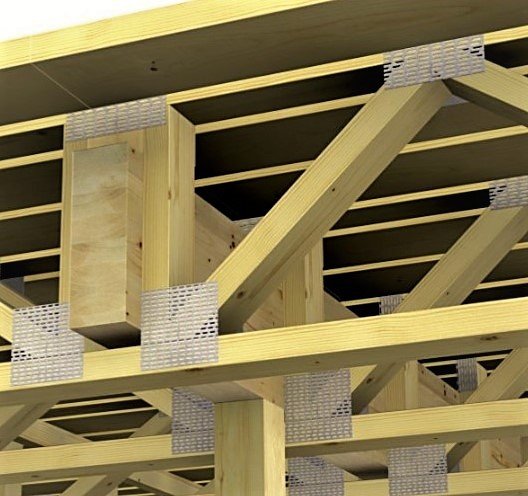
IMAGE: Lattice beam example
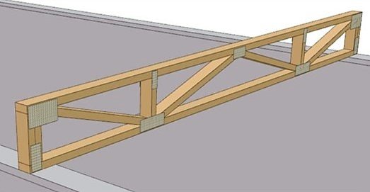
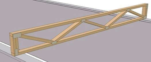
Standing and lying beam elements (chords, rods)
In this context, "standing" and "lying down" refer to how the rod or chord is rotated about its own longitudinal axis. Standing 48 × 48 could just as easily have been called simply 48 × 48 since it is square. The images below show 48 × 48 versus 98 × 48. They also show 48 × 98.
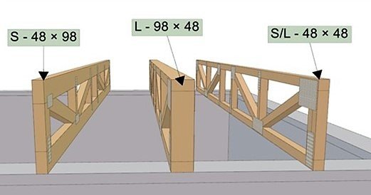
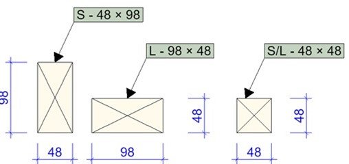
IMAGE: Standing and Lying rods, chords.
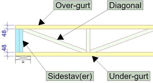
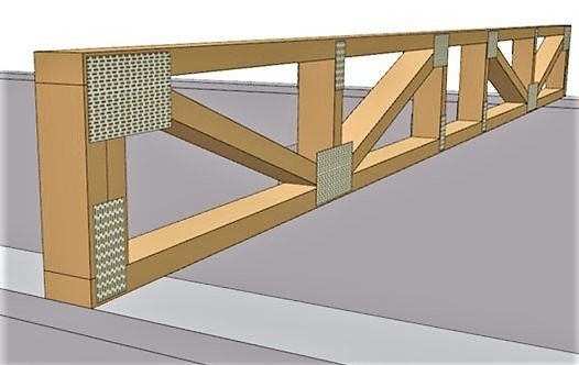
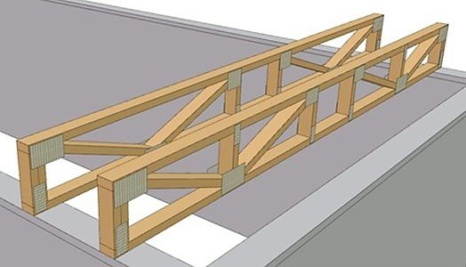
IMAGE: Truss with double side rod due to high loads.
Material dimensions and rotation are chosen, which makes all rods/chords the same thickness. This is necessary in order to secure this with nail plates in the junctions. The pictures below show L – 98 × 48. It has a double side rod e.g. due to load from the upper floor). Sometimes diagonals can also be double. Or that 98 × 98 are used.
The table below refers to the preparation with a view to the comfort criteria.
Part of the idea of making floor trusses (lattice beams / hollow box) is to hide plumbing. At 250 mm in height, the free height between chords will be 154 mm. Ventilation ducts in homes often reach 160 mm, more in other buildings. Sound traps tend to take up even more space if they cannot be placed parallel to and between the floor trusses.
Most often, one has to pay attention to screed (submerged) in wet rooms as well. It is therefore more relevant to use heights greater than 250 mm on floor trusses. If there is no need to hide plumbing, or there is talk of smaller dimensions than 160 mm, low floor trusses can be used. The trusses are, of course, also applicable in roof structures.
Diagonall beams in the truss with additional vertical beams is a solution where one wants to use cross braces. Transverse stiffening increases rigidity this way. This is applicable where you want the lowest possible height. Diagonals only results in a zig-zag pattern.
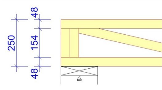

TABLE: Outtake of “Table for trusses, timber hollow box, comfort control”, see the full table here
You can also add a space or “opening” in the center.
Openings are usually placed in the middle and is a space or regions without an oblique diagonal. This allows for e.g. larger ventilation ducts than between other diagonals.

Alternative design with steel diagonals (Posi-Strut)
There is a possibility of manufacturing lattice beams with steel diagonals. We envisage that it is something that will become more and more relevant in the future, even though it is not so widespread in Norway today.
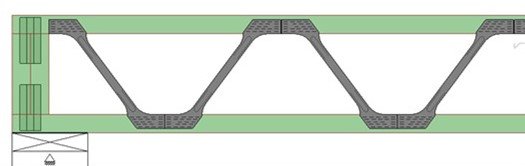
IMAGES: Lattice beams with timber chords and posi-struts
Custom dimensions
Lattice beams are manufactured to custom dimensions. Height, length and diagonal guide vary. Heights in the table are indicative so that you know approximate height based on span.
For example, the height can just as easily be 446 mm as 450 mm if it is suitable for the project in question. 446 is 2 × 223 Then you can use 2 pieces 48 × 223 one above the other as edge beams in the beam layer.
Parameters and applications of the component
The status after the summer project is that the lattice beam can be adjusted in relation to parameters that allow many user-defined and situation-dependent applications. This includes the fitting of nail plates as shown the following:
IMAGE: Tekla Structures component for truss beams. (Click for larger picture)
More features are desirable for increased usability and production of "super components". Finished elements from the factory with widths up to 2.4m and with c/c 600mm and 300mm.
Parameters that may be desirable in the future:
Be able to choose hollow box elements up to 12m length
Adjust length from first vertical rod to first node
Distance between hubs
Automatic insertion of transverse stiffeners at given lengths
Currently, nodes are distributed as a fraction of the length on the basis of the number of compartment/spacing in the beam up to a maximum of 8 diagonals or a total of 4 spacings.

IMAGE: Timber truss beams.
IMAGE: Tekla Structures component for lattice beams. (Click for larger picture)
Features of the Timber ribbon in Tekla
Based on the Swedish tab for Timber, the students have suggested improvements:
Column
Column is a function that basically works well if it can have a standard configuration set to the material catalogue where densities for the wood are updated. An updated profile catalogue that has standard profiles from wood retailers is added, I-beam also has its own plugin on Tekla warehouse from Masonite.
Regarding glulam profiles, it is perceived as easier to simply Type the dimensions B*H or H*B according to what you want, as it is virtually unlimited which measurements are used based on the situation.
Beam
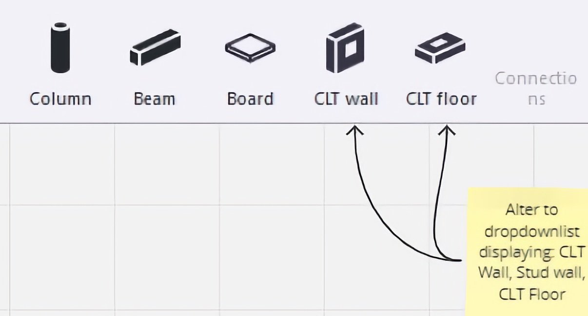
IMAGE: The Timber tab/ribbon proposal
Because of the similarities to Column, we look at the same layout for Beam as mentioned above.
Board
Board will basically be boards of various materials that also extend beyond wood as the material. For example, Plywood (OSB) is entered under Misc in the material catalogue and is therefore perhaps appropriate to use as the default material configuration for the Board function.
Wall
In the picture above, we see CLT Wall as an option. Here it may be appropriate to have a split alternative such as just Wall that splits into alternatives in relation to whether it is solid wood or studs that are to be placed in the model.
The Stud Wall function should contain similar functions to the plugin from Mainpart, where the user can access automatic placement of studs in an element with standard center-center 600mm. If the user double-click or shift-click the wall, a dialog box (similar to Floor layout) will appear to allow customization for recesses to doors and windows, adjustments to spacing, choice of timber frame (I-beams, construction timber, glulam, ISO3) and options for insulation, vapor-barrier/brake and material quality. SINTEF Building and Infrastructure has several pre-accepted solutions that could be included as “quick selections” or “quick-picks” for layers.
CLT Wall should have similar features as in the Swedish layout. But it may be appropriate to also be able to specify;
Fiber directions with parallel to longitudinal direction as standard.
Slat specifications such as material type/quality, thicknesses and number of layers.
Surface treatment with VV (Visible/Visible), NN (not Visible/Not Visible) and VN (Visible/Not Visible.).
Hole and recess cuts in the same way as with the Stud-Wall function.
Layers function with option for selection of pre-accepted solutions
Floor/flooring
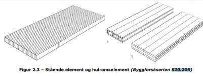
IMAGE: Standing beam elements, and hollow box/core elements
Here, a separate Wood-Floor Layout can be to the benefit of the user, with e.g. an option to choose pre-accepted solutions from SINTEF. Easily place out the space they want with a complimentary dialog box that lets the user choose:
Beam layer/floor divider tools for a range of various profiles with insulation layers, acoustic layers, drywall, plaster, convection barrier, vapour barrier depending on whether it is either basement, floor or roof. Ready-made solutions can have a separate tab with the possibility of customization.
CLT Floor - The user is taken to a virtually identical dialog box to that of CLT wall.
Options such as standing or lying hollow box elements may also be of interest. Some CLT covers have beams of glulam that should also be able to be inserted with dimensions in optional center-center distance as an underlying layer.
Connections
Similar to Bolts and Weld in the Steel tab, the team suggests Connections as a collective term in the interface. Here the customer can find screws, slot plates, timber dowels and an End-Cut tool.
End-Cut divides timber elements into dimensions that are complimentary to fabrication measurements. This function needs specification in the following areas:
Whether there are cavity elements and/or whether it is solid wood or not. Ability to enter length and width measurements.
Polygon cut. This is so that corner elements, stair holes etc. are taken care of. For example, if you specify that it should be cut for solid wood, you can also choose which profile we find in the cut itself. In this way, the factory will be able to know what is the tongue and groove at the same time what kind of cut profile is desired. Here, information must be collected about which cuts the manufacturers offer.
Component Binder
A functionality that offers a modular option in the form of associating selected components with the Component Binder. Widely used components may be typed in a drop-down menu originating from this option.
E.g. it may have a drop-down list with icons of the three most used components. Alternatively, the user can add their own and lock the Component Binder to the given components.
Import and export of IFC
Import and export of IFC files for the production of glulam is a challenge according to several players in the industry. Different use of clash check accuracy (number of decimals etc.) leads to inaccuracies when transferring between engineering and fabrication.
Angles and collisions in the model lead to a need for corrections to the model by the engineers. An ambition for the future should therefore be to find a more seamless transfer of such model drawings to machines that produce timber elements, whether glulam or CLT.
Summary
It is feasible to design timber load-bearing structures with Tekla as the software works today.
However, with some adjustments and additions, industry terminology and software will harmonize better and help with the following:
✓ Speed up work
✓ Reduce errors
✓ Lower the user threshold
With components in Tekla for automation of the design process according to standard solutions developed by the industry, the work in Tekla will be even more efficient and help reduce the cost of the projects.
This will also contribute to efficiency in production and easier quality control and lead to a reduction in the cost of using timber!
We look forward to continuing this work in collaboration with the industry. Please contact us if you would like to contribute or discuss timber opportunities in Tekla!
Thank you!
The team want to thank the following companies for great input and contributions!