Using laser scanning to check floor flatness
VIDEO: How to perform Floor Flatness checks with laser scanner and in-field analysis to be able to identify issues right there and then!
Floors are never 100% flat, but they need to be flat enough to meet the requirements in standards and regulations. Other times there are requirements for an angle related to drainage systems.
To illustrate how easy it is to check and document the conditions of a floor after a pour of concrete, or in this case after everything is finished, we went to a bicycle parking basement to show a practical example of how laser scanning technology can be effectively used in such scenarios!
Setting up the scanner
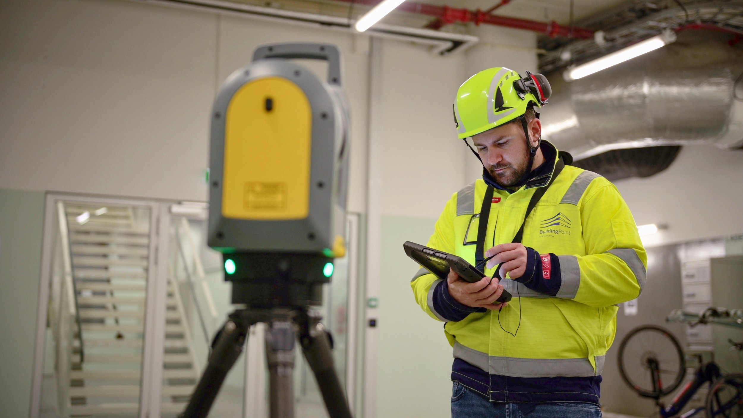
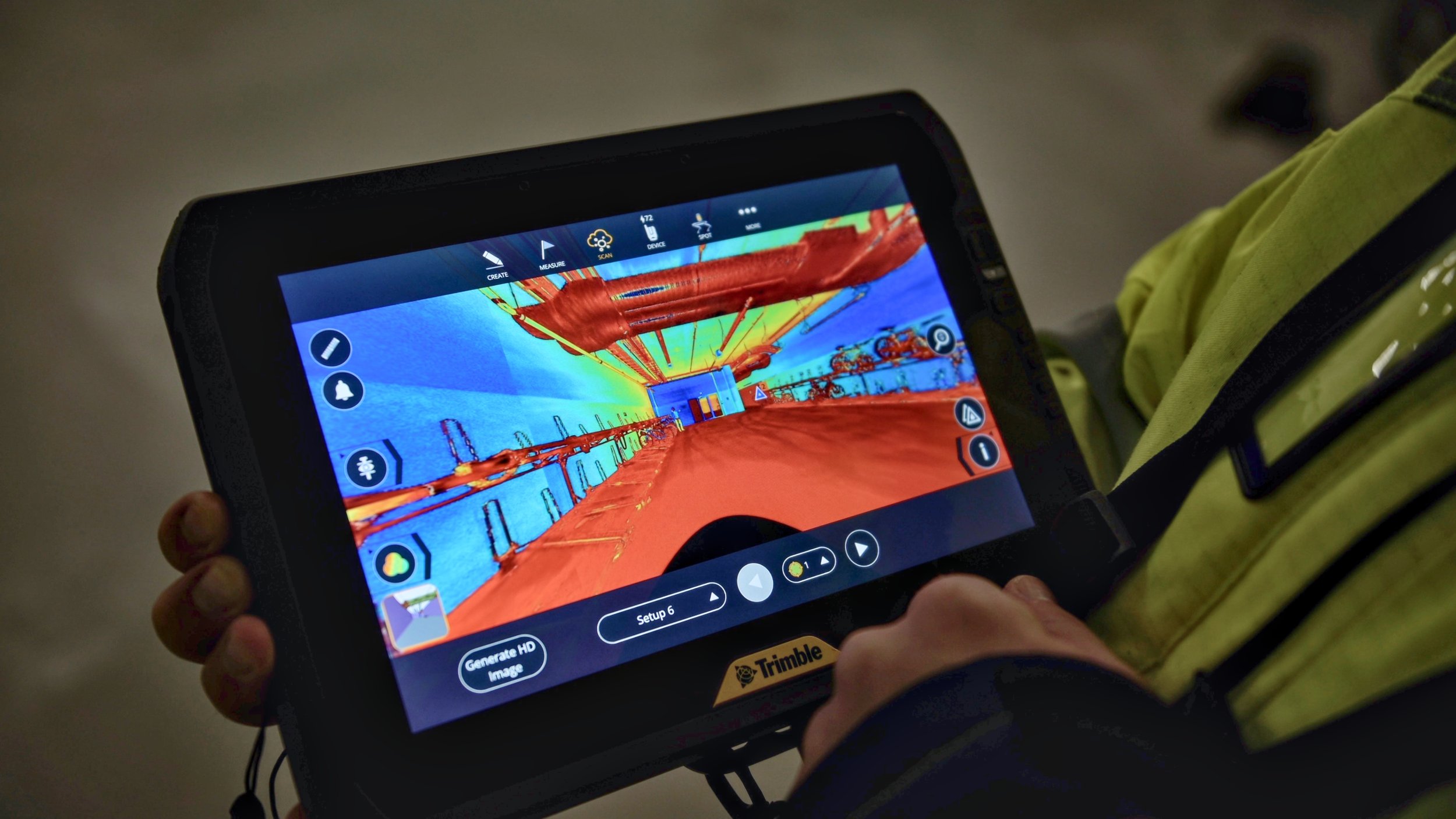
At the core of this demonstration was a Trimble X-series laser scanner, known for its user-friendly features like self-leveling and self-calibrating capabilities.
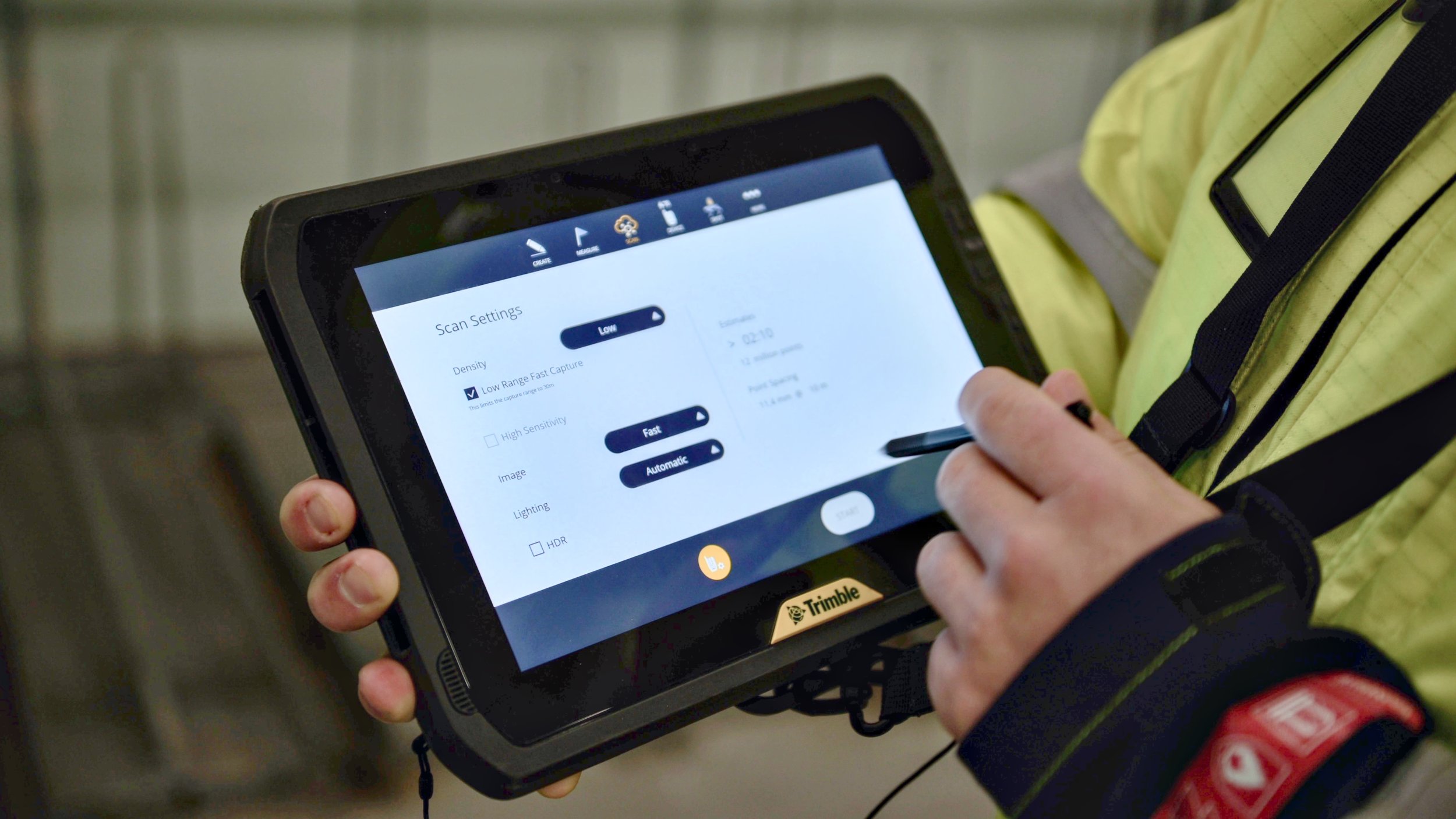
In just seconds the scanner can be set up on a tripod and linked to a tablet for data capture. In this case we chose the «low» settings, and the scanning process was completed within one to two minutes, showcasing the efficiency of the technology.
Data Analysis and Interpretation
IMAGE: Trimble T10X tablet with Trimble FieldLink software displaying the floor flatness results. One can clearly see that the blue area beside the drain is lower than the drain itself.
The analysis phase was conducted using Trimble FieldLink software, directly on the tablet. This phase involves setting a reference height and analyzing the elevation levels of the floor. The software provided a color plot visualization, which helped in assessing the floor's flatness more intuitively.
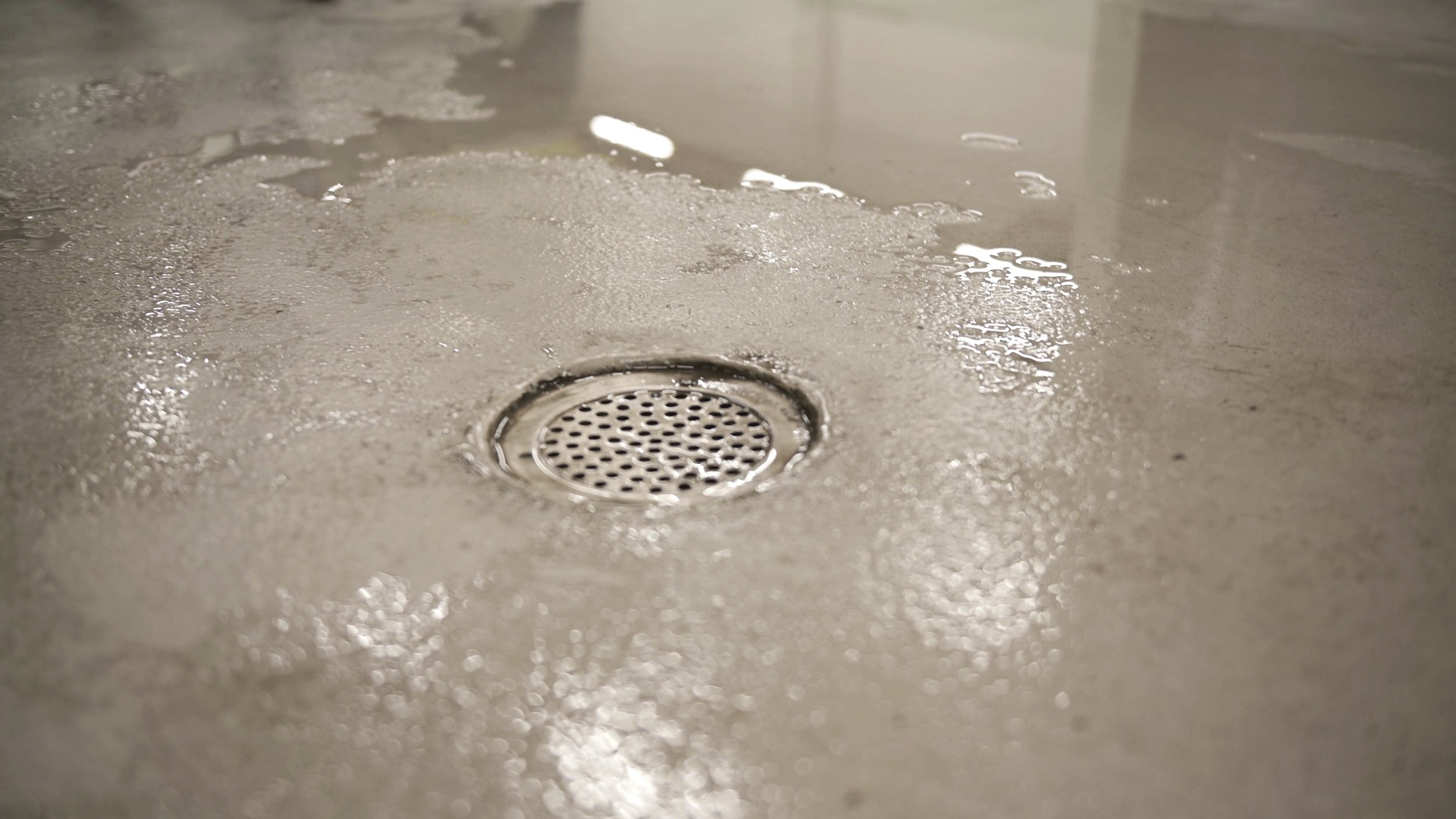
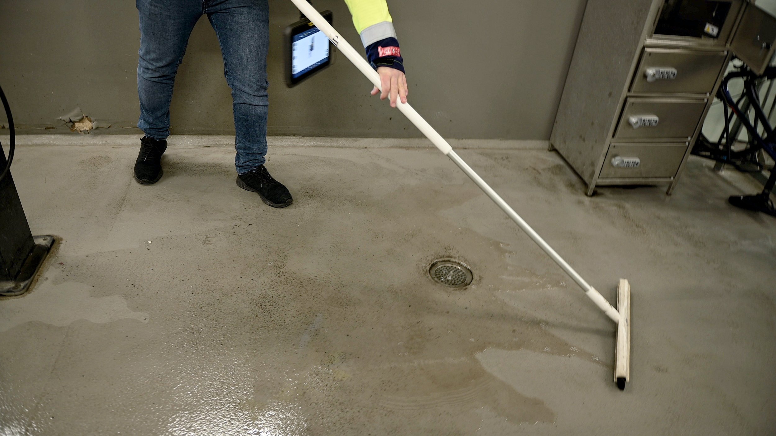
From the initial scan, the team observed an unexpected low area next to the drain, which indicated potential water accumulation problems. Further scans of the entire basement revealed more areas with similar issues. This highlighted the scanner’s capability in identifying discrepancies that might not be easily noticeable otherwise.
"
There will be a problem with water accumulation if nothing is done about it! We did a few more scans, and we can see other similar issues in the rest of the basement…
- Mikkel (after mopping up water beside the drain)
Documentation and Reporting Made Easier
IMAGE: Floor Report example, created automatically in Trimble FieldLink
One of the significant benefits of using this technology is evident in the documentation and reporting phase. The Trimble FieldLink software automates the creation of detailed reports, including specific coordinates of the elevation points.
This feature is particularly useful for communicating findings clearly and accurately. Additionally, one can use the laser pointer on the scanner to point to specific coordinates where there may be a need for correction. By mapping out several points, one can precisely indicate regions that are out-of-tolerance.
For more detailed analysis, Trimble RealWorks offers advanced functions for handling point clouds.
Using AR
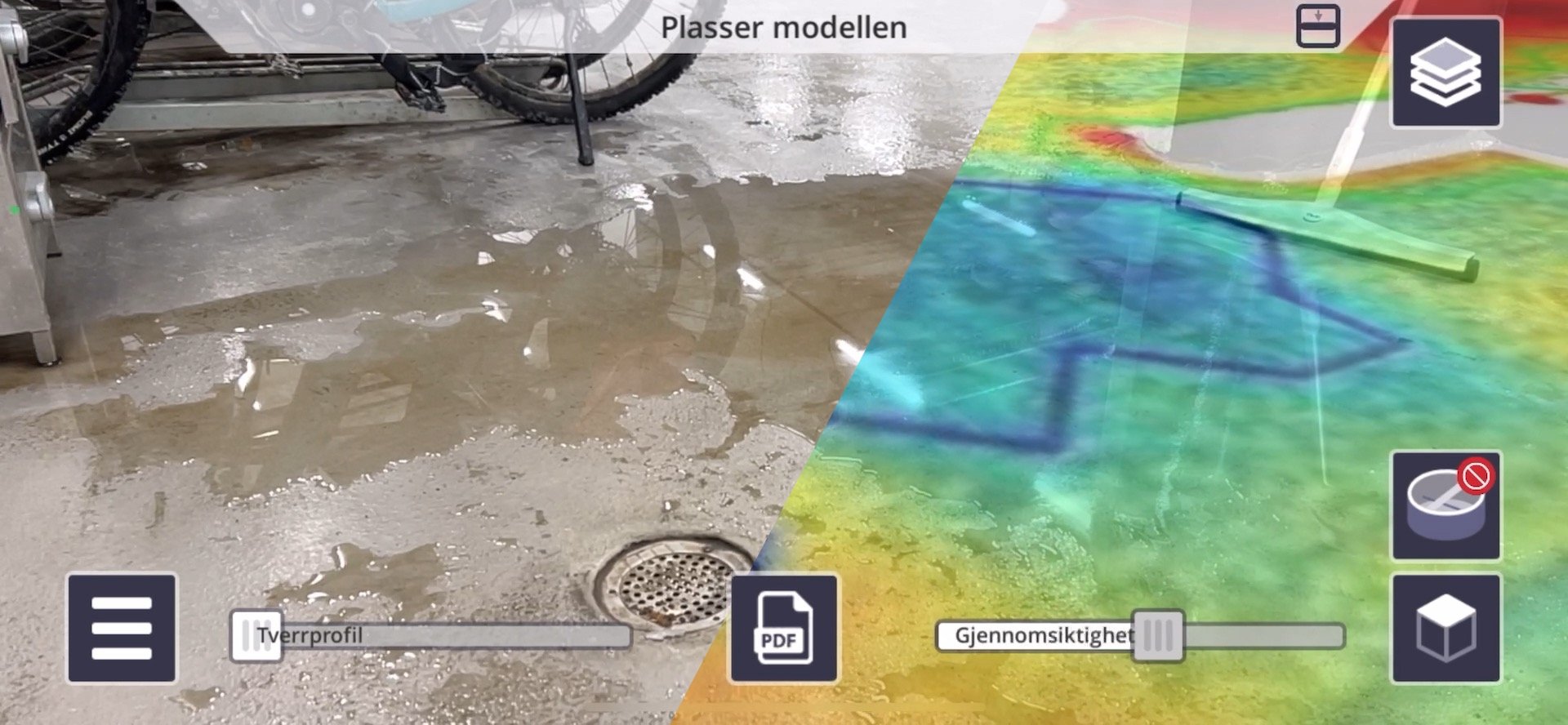
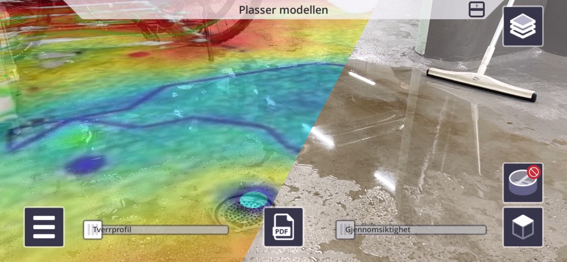
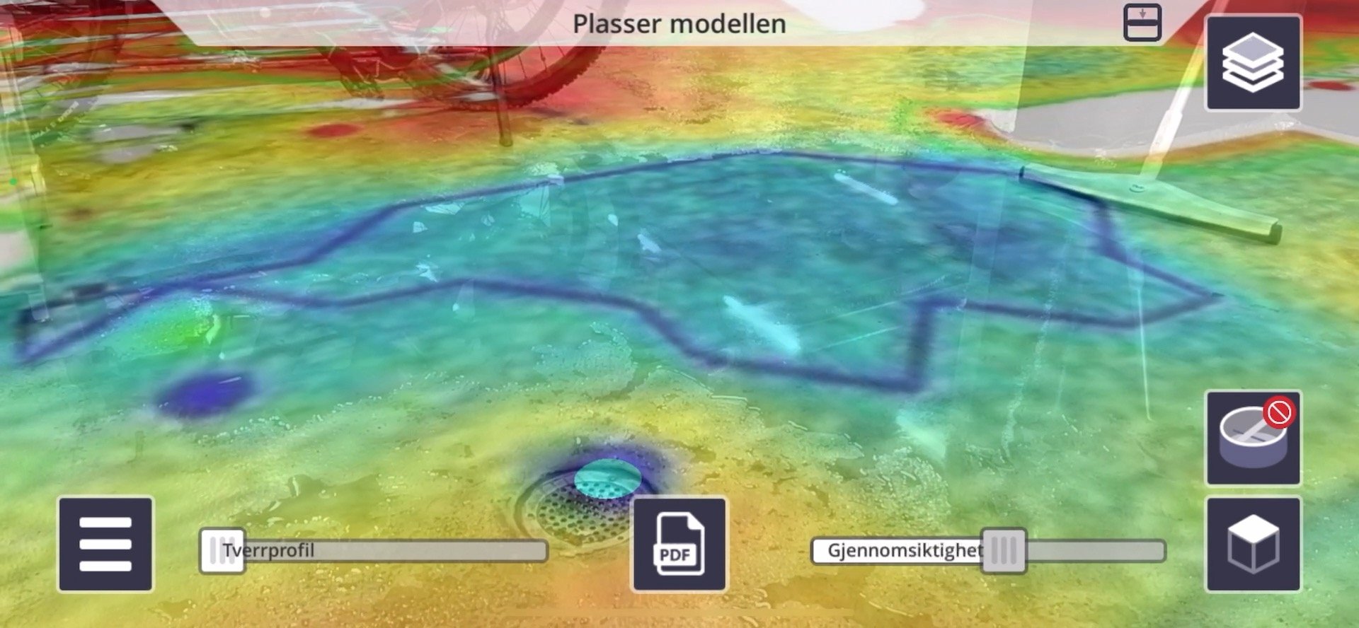
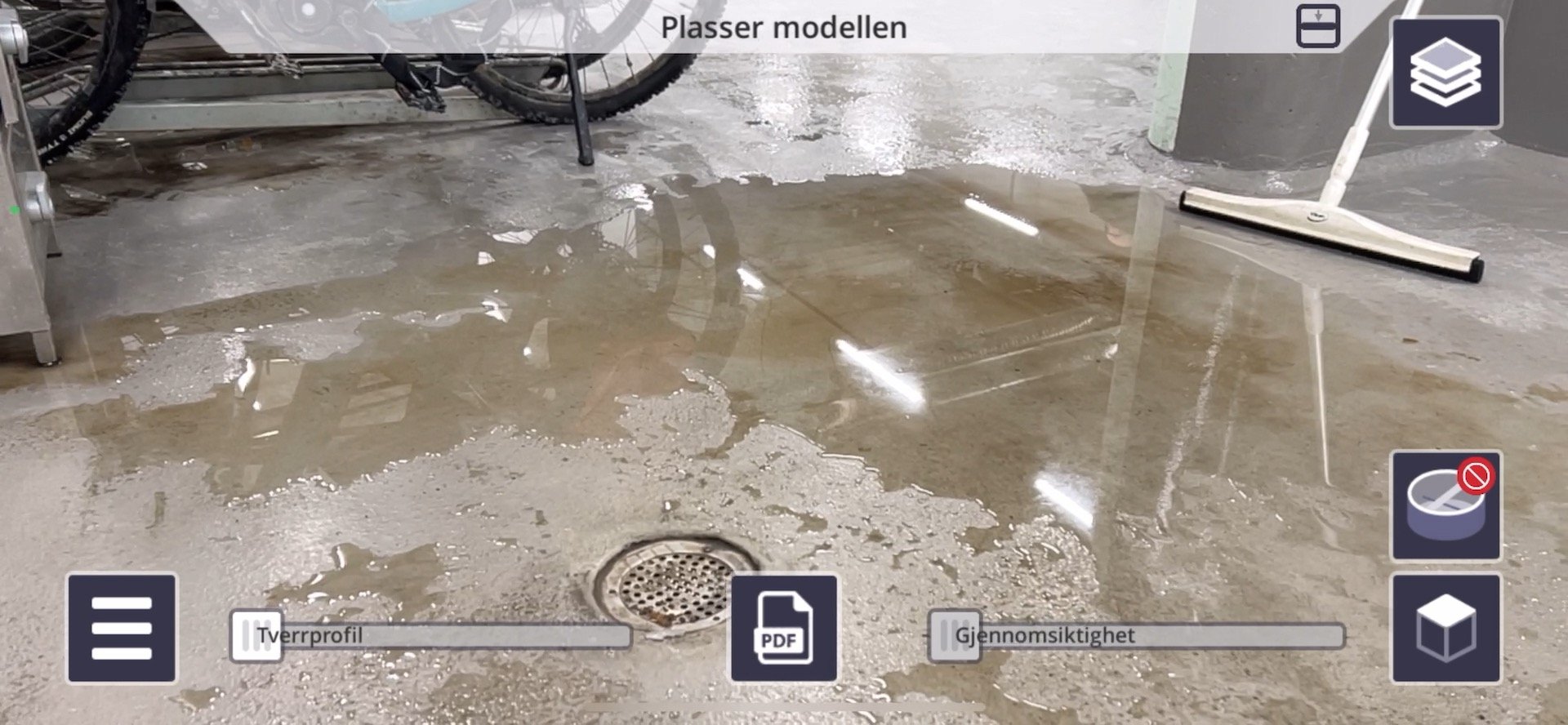
The integration of the floor analysis results with Trimble Connect AR allows for an augmented reality overlay, providing a more immersive understanding of the data as demonstrated in the video.
Accurate, efficient, and easy!
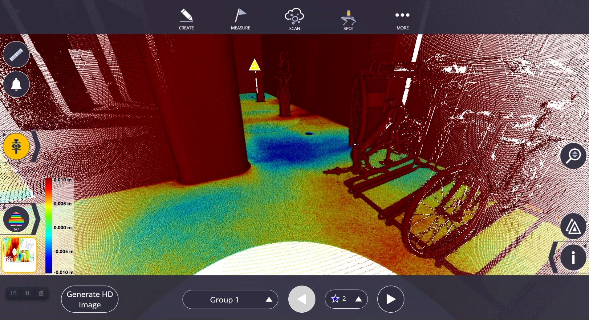
IMAGE: Trimble T10X tablet with Trimble FieldLink software displaying the Floor Analysis results with contours and reporting points.
This demonstration underscores the effectiveness of laser scanning in assessing floor flatness.
With a single scan producing twelve million points in a short time, the technology proves to be a time-efficient method for floor evaluation, and it adds a valuable tool to the construction professional’s arsenal, promoting more accurate and reliable assessments in building projects.
...and it might save you rework, extra costs, and a bad reputation!
How to get started?
Reach out to us, let’s talk!
OTHER ARTICLES