Point clouds in Tekla - why, what and how to do it!
VIDEO: Presentation of Point Clouds in Tekla Structures - why, what and how! Michal from BuildingPoint Scandinavia gives you a demo of how to import, align and clean up point clouds, as well as what you can do in terms of analysis and use of scan data in Tekla!
Many engineers would like to use point clouds more in their project - but some feel that using special software for point clouds can be a threshold too high… So why not bring the point cloud directly into Tekla Structures?? Watch the presentation and demo to learn more and get started!
Why scan?
Before diving into the “what” and the “how”, let’s discuss a few things that motivates the use of scanning. Scanning can be used in all phases of a construction project, from the bidding phase, through pre-engineering and design, during erection/construction, and for as-built documentation.
Preliminary design
IMAGE: Scan of a room with process equipment along with a Tekla model. This helps the engineer quickly understand limitations and constraints on the site.
(Click for larger image)
During the preliminary design phase of a construction project, particularly in refurbishment and modification projects, it is beneficial to incorporate scanning into the workflow at an early stage to ensure that one can understand the starting conditions well.
Conducting scans even before presenting a bid allows for the generation of more accurate bids. This accuracy not only benefits the contractor who will provide a bid with cost estimates based on facts and less “guesstimates”, but it also expedites the decision-making process, leading to faster project initiation.
Starting the project with a detailed scan of the site also offers a head start. The scan provides a clear and comprehensive understanding of the site's conditions, allowing for more informed design and engineering decisions. This, in turn, can accelerate the overall project timeline!
Additionally, the utilization of scans can reduce the time needed for survey work. By capturing detailed data upfront, the project team can also avoid revisiting the site for additional measurements. This not only saves time but also minimizes disruptions to ongoing work.
During production
During production and fabrication, the incorporation of scanning offers numerous advantages that may contribute to the overall quality and efficiency of the process.
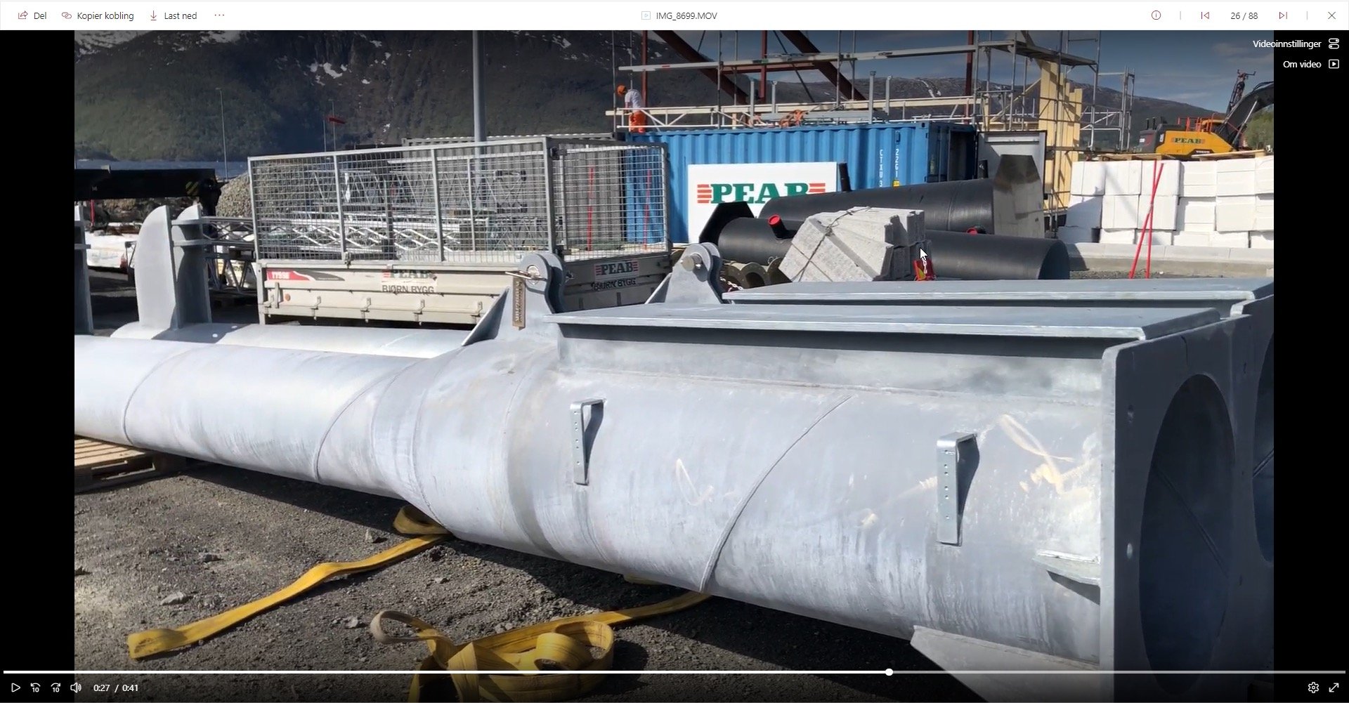
One key benefit is the ability to perform scans after welding, prefab casting, or similar manufacturing stages.
These post- or during production scans serve as a critical quality control measure, allowing for the early detection and identification of errors or quality issues. By catching these issues promptly, corrective actions can be taken, preventing potential downstream complications and ensuring the final product meets required standards.
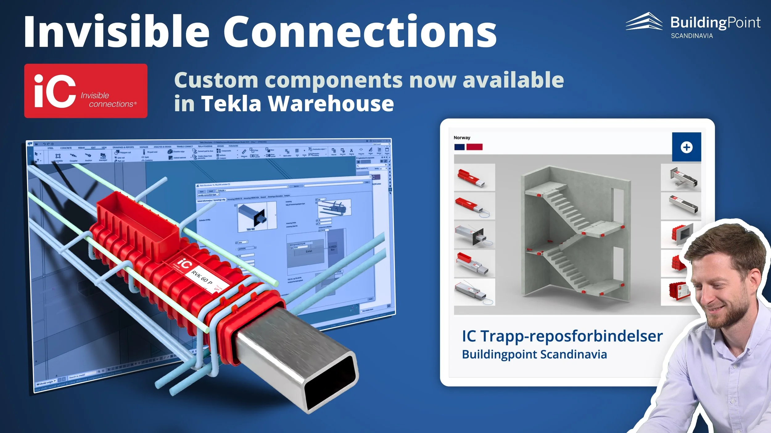
IMAGES: Why not scan at the workshop? A point cloud of the structure can help find errors and mistakes, and it can be used for “virtual assembly” on the construction site to see if it will fit even with deviations (if there are any)
Another valuable application of scanning in production and fabrication is to verify the fit and alignment of components. Scanning can be used to ensure that assemblies will fit seamlessly at the construction site. This proactive approach minimizes the risk of on-site adjustments and delays, promoting a smoother installation process.
Additionally, the documentation represented by the point clouds offers additional value . Scans provide a detailed and accurate record of the production and fabrication processes. This documentation is great for quality assurance, compliance reporting, and even future reference.
At the construction site
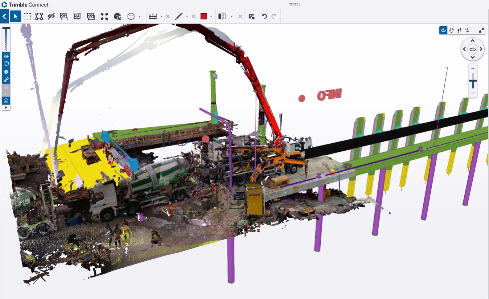
IMAGE: A point cloud overlaid on the BIM model in Trimble Connect
One key benefit of scanning during the course of a construction project is the capability to identify errors or problems at an early stage.
Frequent on-site scanning allows for real-time monitoring and inspection, enabling project teams to pinpoint issues as they arise and even use the scan to revise the design, or make adjustments to the design, based on accurate data from the scan data. Early detection of problems is crucial for prompt corrective action, preventing project setbacks and ensuring timelines are maintained.
On-site scanning can serve as a tool for progress documentation. By regularly scanning and capturing data throughout the project, comprehensive records of progress can be generated. This documentation not only assists in project tracking but also provides a historical reference for future needs, such as audits, reports, or potential legal/contract considerations.
Additionally, on-site scanning facilitates the creation of as-built documentation. This involves capturing precise details of the constructed elements, ensuring that the final product matches the design and engineering specifications. As-built documentation is essential for record-keeping, facility management, and any future modifications or renovations.
What can you do in Tekla?
Naturally, tools like Trimble FieldLink and Trimble RealWorks are great for working with scan data! But since the point of this article is to highlight what can be done for the “casual user” of point clouds who spends most of her/his time in Tekla, we will focous on that!
In Tekla Structures various scanning analysis capabilities are available. Here's a breakdown of the most typical uses of point clouds in Tekla without using additional specialist software!
Visual checks
Clash Checking: Tekla allows you to perform clash detection between the point cloud data and the model.
This helps identify clashes or conflicts between the proposed design and the actual site conditions, ensuring that elements do not intersect or clash with each other.
Identify errors or mistakes: Beyond clashes, you can visually inspect the point cloud data to identify other errors or discrepancies. This includes checking for missing elements, alignment issues, or any anomalies that may require correction.
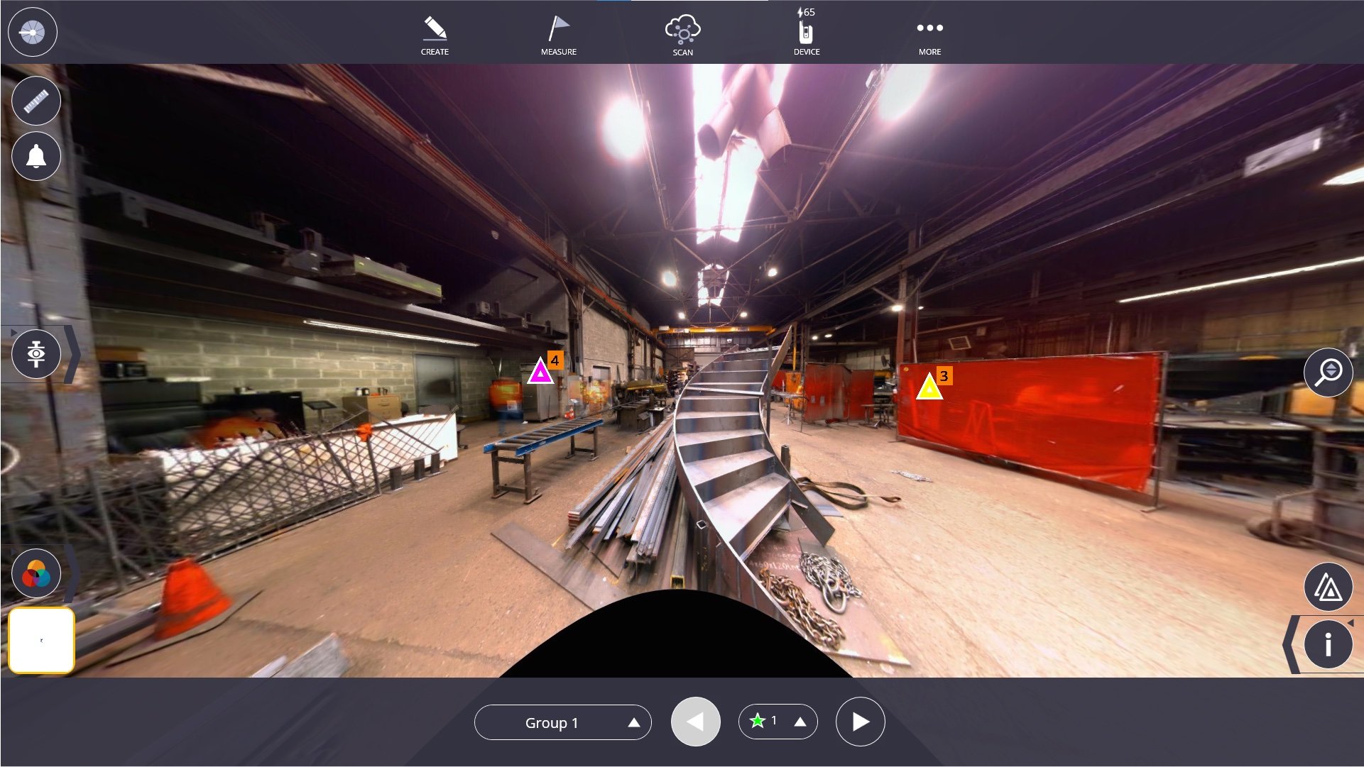
And why not scan large assemblies and do a “virtual build” to check if they fit before you start the actual assembly on the construction site?
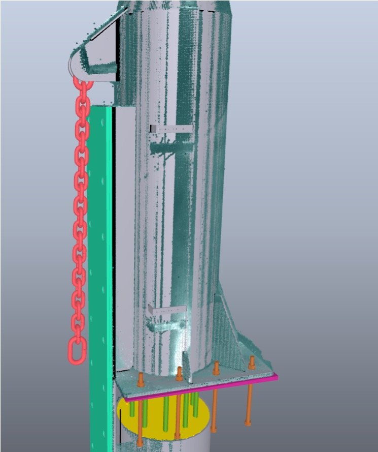
IMAGES: Scanning of this steel column ready for assembly on the construction site allows you to do a “virtual assembly test” in Tekla to quickly check if the structure will fit, or if there will be any problems.
Dimensional checks
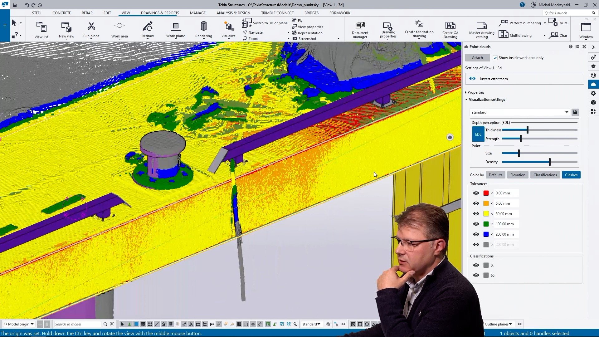
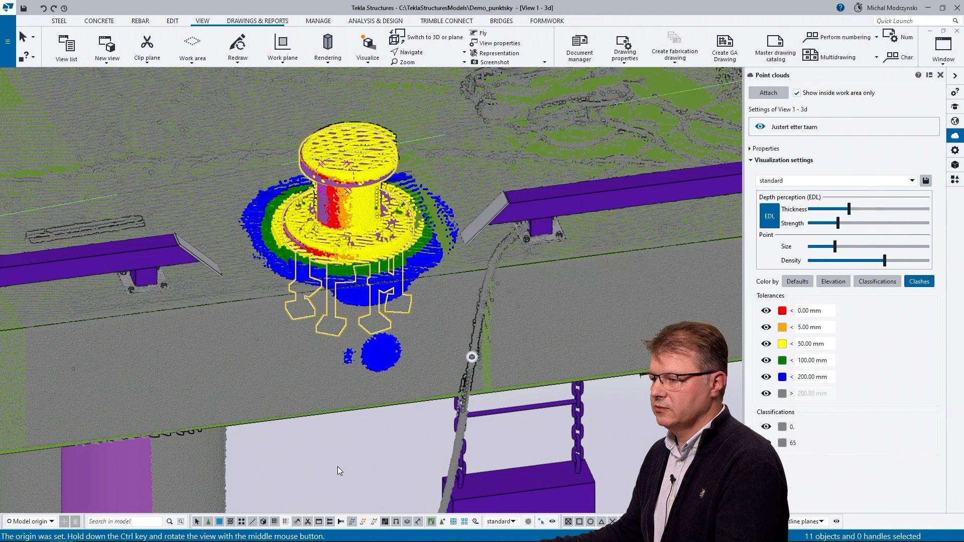
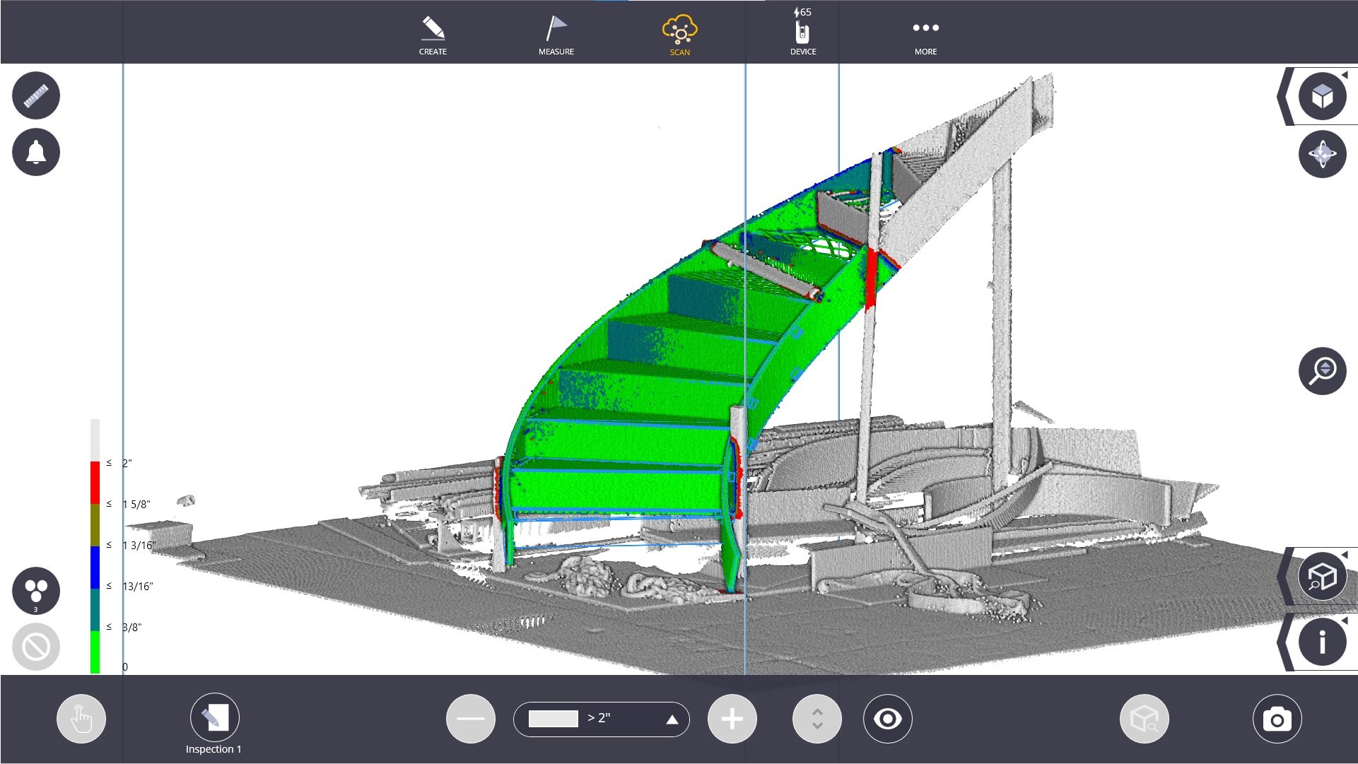
IMAGES: The “Clashes” analysis in Tekla lets you visualize the distance between the point cloud and the geometry, allowing for some basic “floor flatness” analysis and easy discovery of deviations. (Screenshots from the demo video in this article)
Measure distance between point cloud and geometry: Tekla enables you to measure distances between the point cloud data and the model geometry!
This functionality allows you to find deviations between the as-built conditions and the design specifications. It's useful for ensuring that constructed elements align with the intended dimensions.
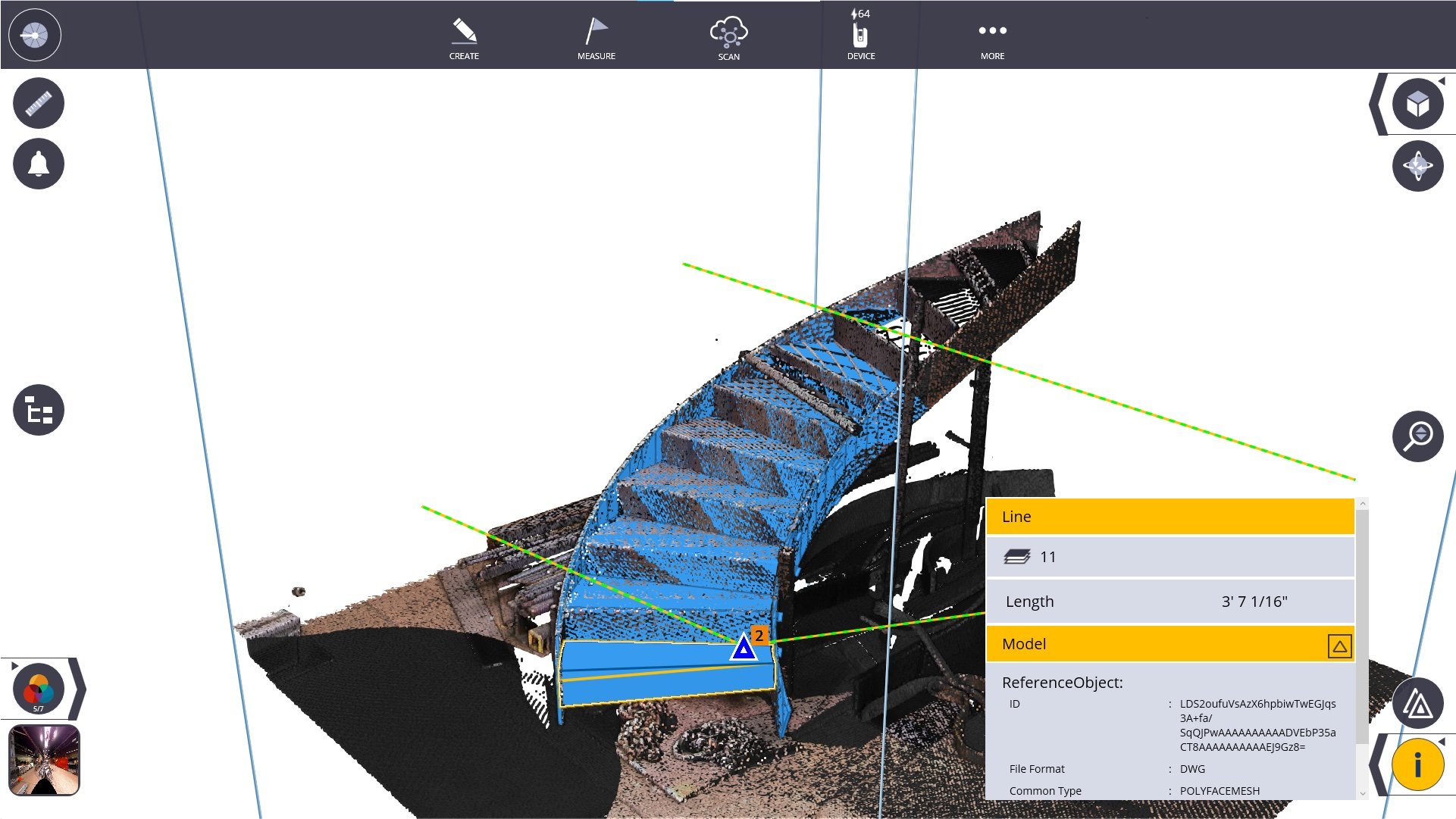
Connect the Tekla model to scan points
Snap to the points and create models attached to the "real world": One powerful feature of Tekla is the ability to use the point cloud data as a reference for design.
You can snap to the points in the point cloud and create a model that aligns with the "real-world" site conditions. This ensures that your design is closely tied to the actual environment, improving accuracy and minimizing discrepancies.
In summary, Tekla Structures offers a range of scanning analysis capabilities that includes visual checks, clash detection, dimensional checks, and the integration of point cloud data into the design process to enhance the accuracy and efficiency of structural engineering in construction projects.

IMAGE: Overlay the scan on the Tekla model and take measurements between as-built and design.
How to use point clouds in Tekla
Using scan data in Tekla Structures involves several steps to effectively integrate the point cloud information into your modeling and analysis processes. To see the process, please watch Michal’s presentation in the video on this page. The basic steps are these:
1. Import the point cloud
Open your Tekla Structures project or create a new one.
To import the point cloud data, go to the "Model" tab.
Select "Import" and choose the point cloud file format you have (e.g., .XYZ, .PTS, .LAS, .E57).
Configure import settings, such as the coordinate system and unit scale, to ensure proper alignment with your project.
2. Align the scan manually (if necessary)
After importing the point cloud, you may need to manually align it with your project's coordinate system or the existing model.
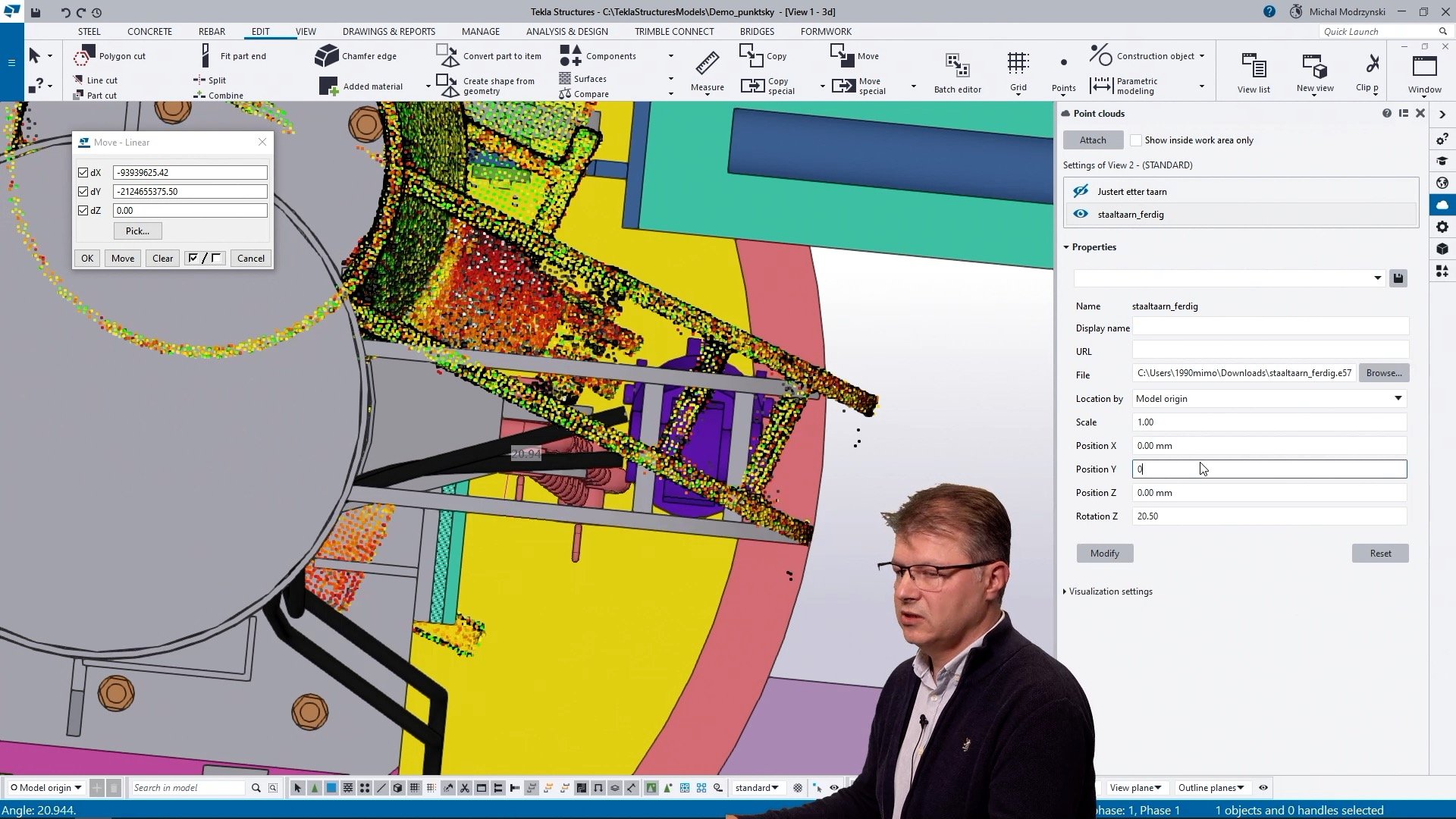
Tekla provides tools for translating, rotating, and scaling the point cloud to match the project's real-world coordinates. Use these tools to ensure proper alignment. (See the video!)
3. Reduce the size of the point cloud
Point cloud data can be quite large, and for efficient modeling and analysis, you may want to reduce its size.
IMAGE: The Point Cloud Manager is an easy-to-use software to reduce the size of the point cloud. The functionality is limited, but helps you cut down the size of the point cloud before you import it to Tekla. (click for large picture)
Point Cloud Manager
Customer with an active Tekla subscription can download the Point Cloud Manager to crop the the point cloud to remove unnecessary or excessive data points while preserving critical details before importing it to Tekla.
Although you can limit the size of the point cloud within Tekla (see the demo in the video) is is better to do the initial clean-up in Point Cloud Manager, in our opinion.
This step helps improve system performance and streamlines the modeling process.
4. Analyze and review the model or use for further modeling in Tekla
Once the point cloud is imported, aligned, and optimized, you can use it in various ways:
Analysis: You can use the point cloud data to perform clash detection, dimensional checks, and visual inspections to identify discrepancies between the as-built conditions and the design as described above in this article.
Modeling: You can use the point cloud as a reference to create new structures or modify existing ones. Tekla provides tools for snapping to the points in the point cloud and accurately modeling based on the real-world data.
Documentation:You can generate reports, drawings, and documentation based on the point cloud data to provide a comprehensive record of the project's as-built conditions.
Also refer to the Tekla User Assistance for detailed instructions and tips specific to your version of Tekla Structures!
See the video presentation and demo here!
Interested in more scanning tools?
Consider our newest scanner, the Trimble X9 and more advanced software: Trimble FieldLink, this comes with the scanner, or Trimble Realworks which is your desktop software for advanced point cloud management and analysis!